202 - UML
Class Diagrams
Class diagrams are the backbone of almost every object oriented method, including UML. They describe the static structure of a system.

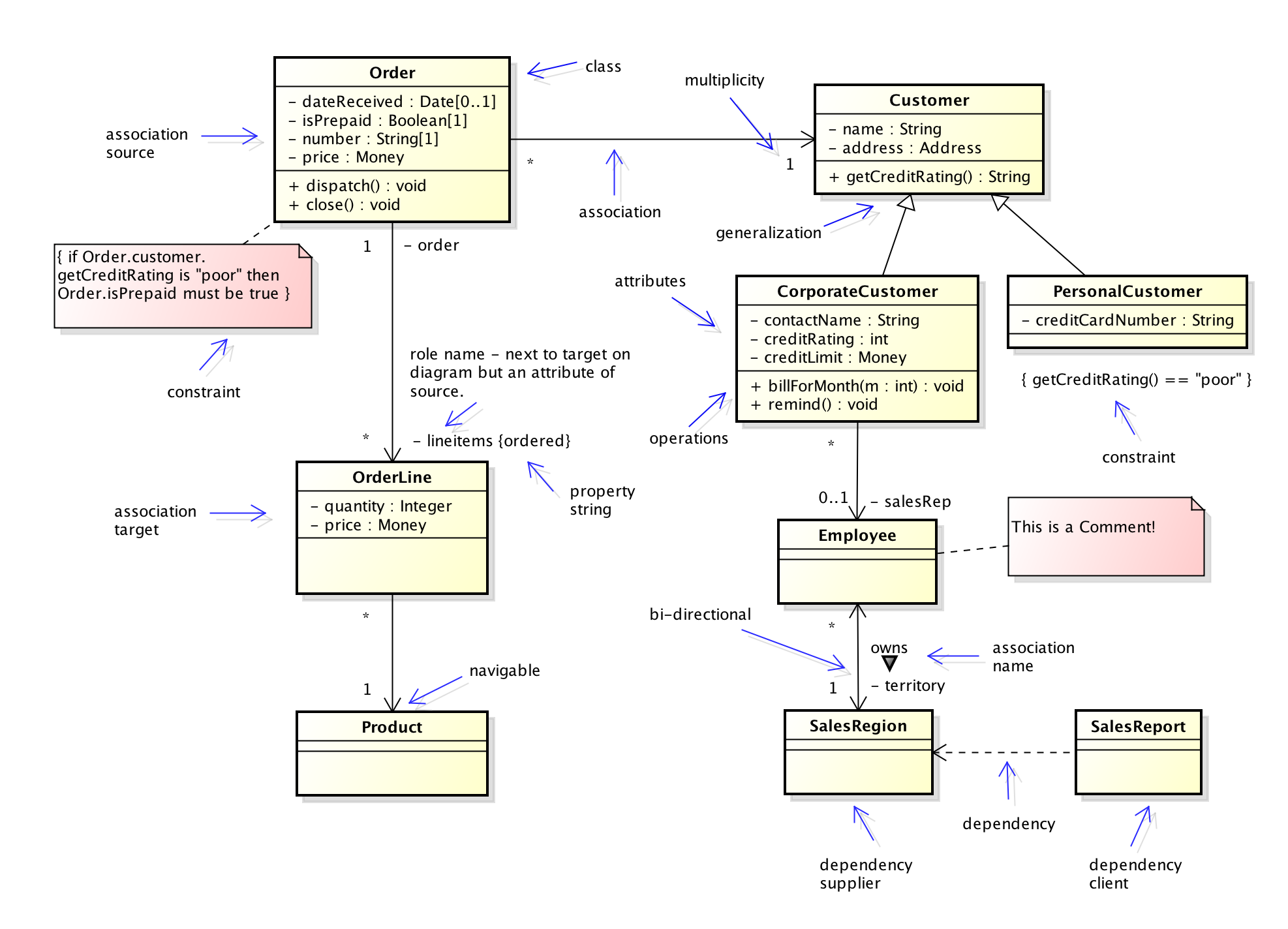
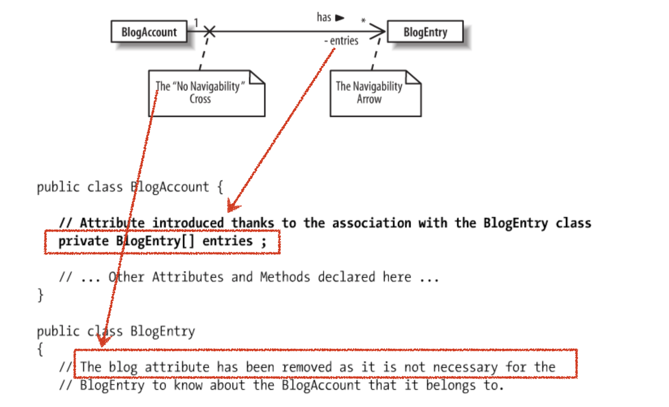
Association: a class will actually contain reference to an object
Sequence Diagrams
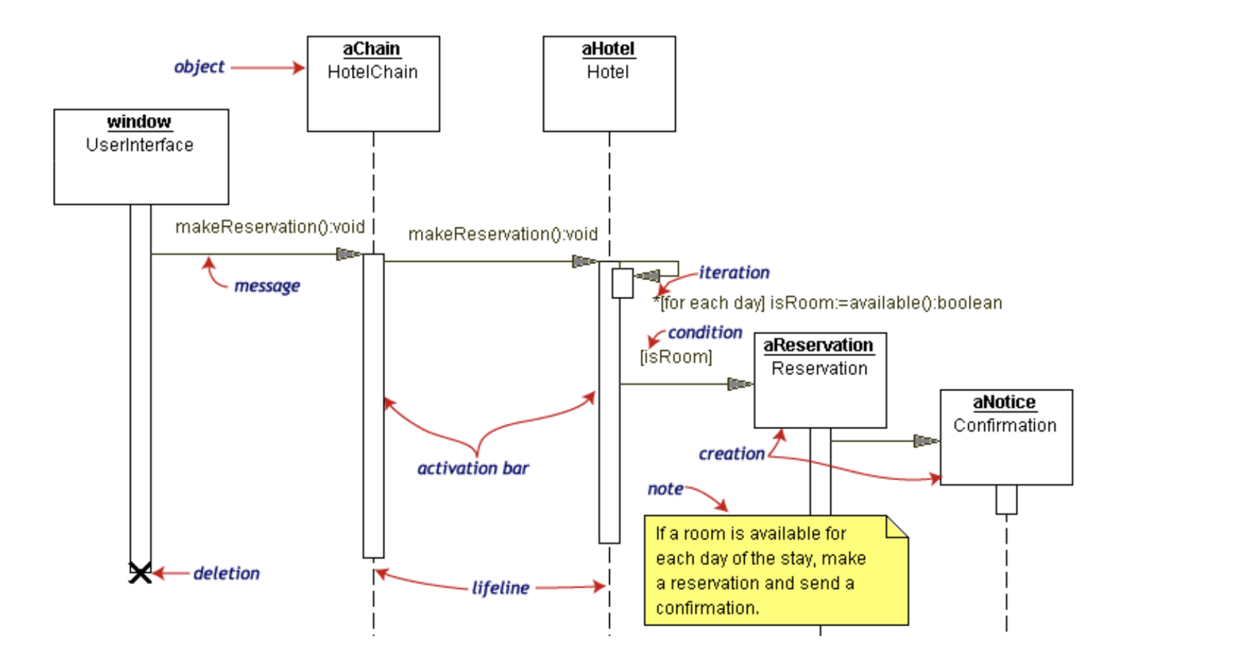
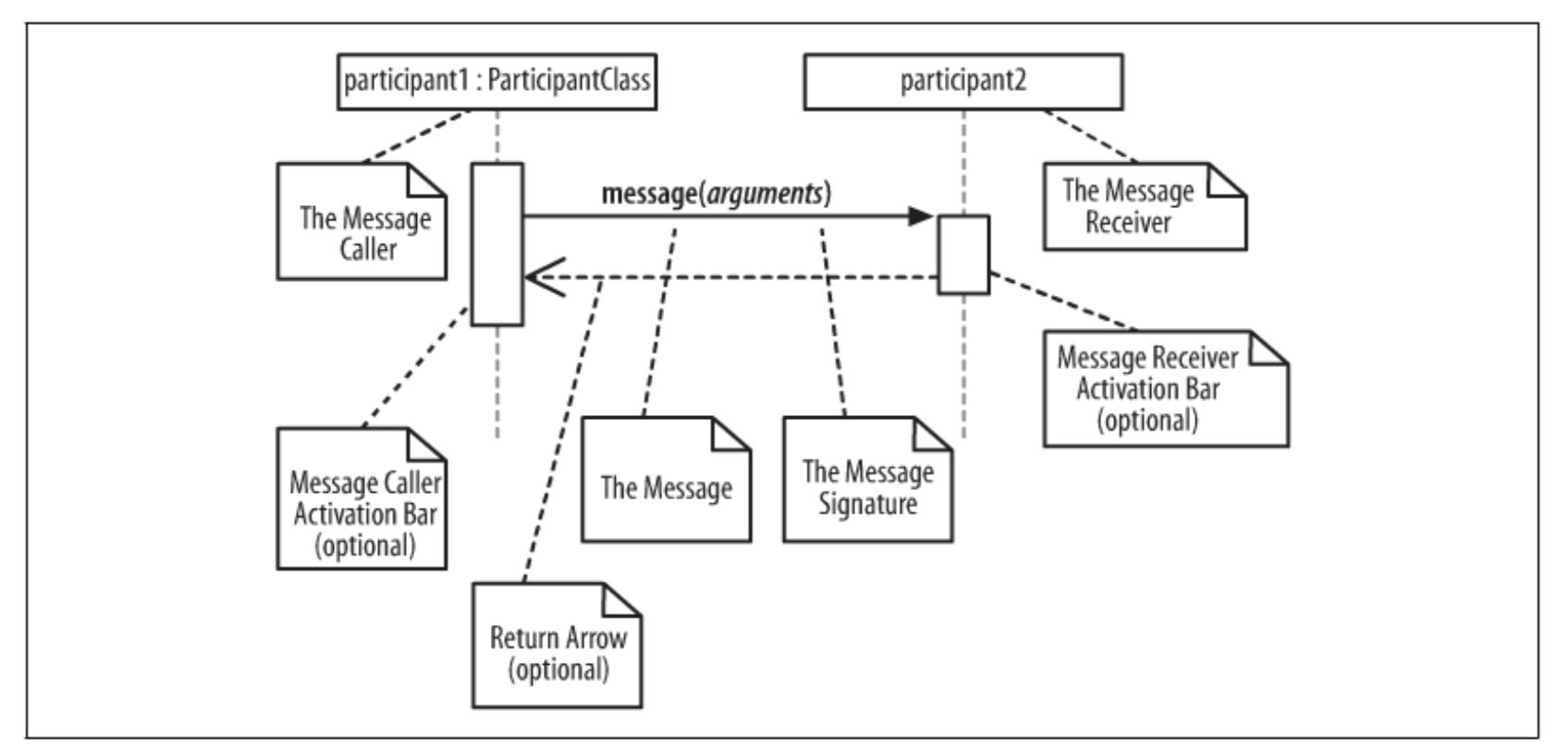
Sequence diagrams describe interactions among classes in terms of an exchange of messages over time.
Activity diagram
modeling the flow of control from activity to activity. An activity represents an operation on some class in the system that results in a change in the state of the system. Typically, activity diagrams are used to model workflow or business processes and internal operation.
☛ swim lanes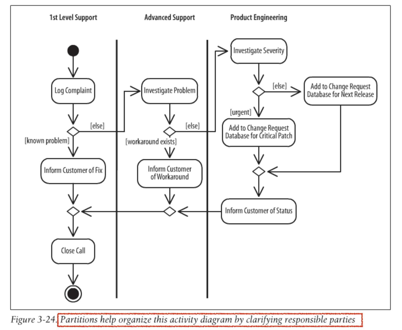
upside-down pitch fork symbol ψ is a call activity node. That is similar to calling a software procedure.
An object node is drawn a rectangle to emphasize it is an important data in this activity and shows which action interact with it.
input/output pin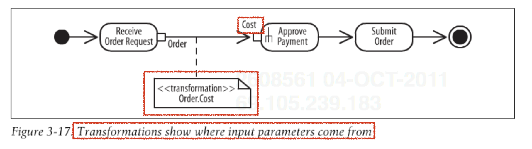 object changing state
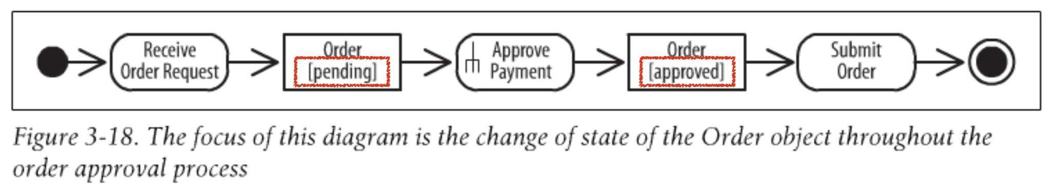
signals represent interaction with external participants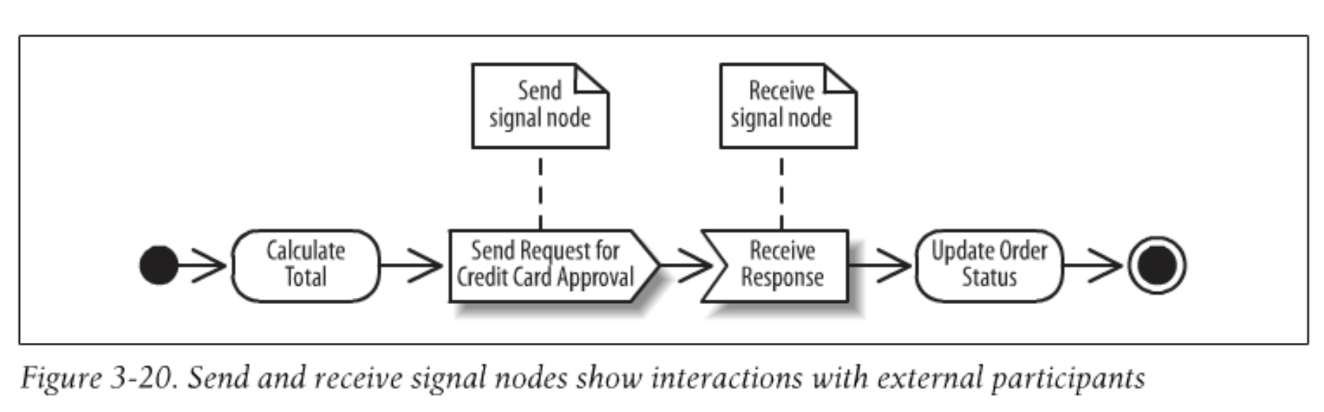 interruption region showing a process that can be interrupted
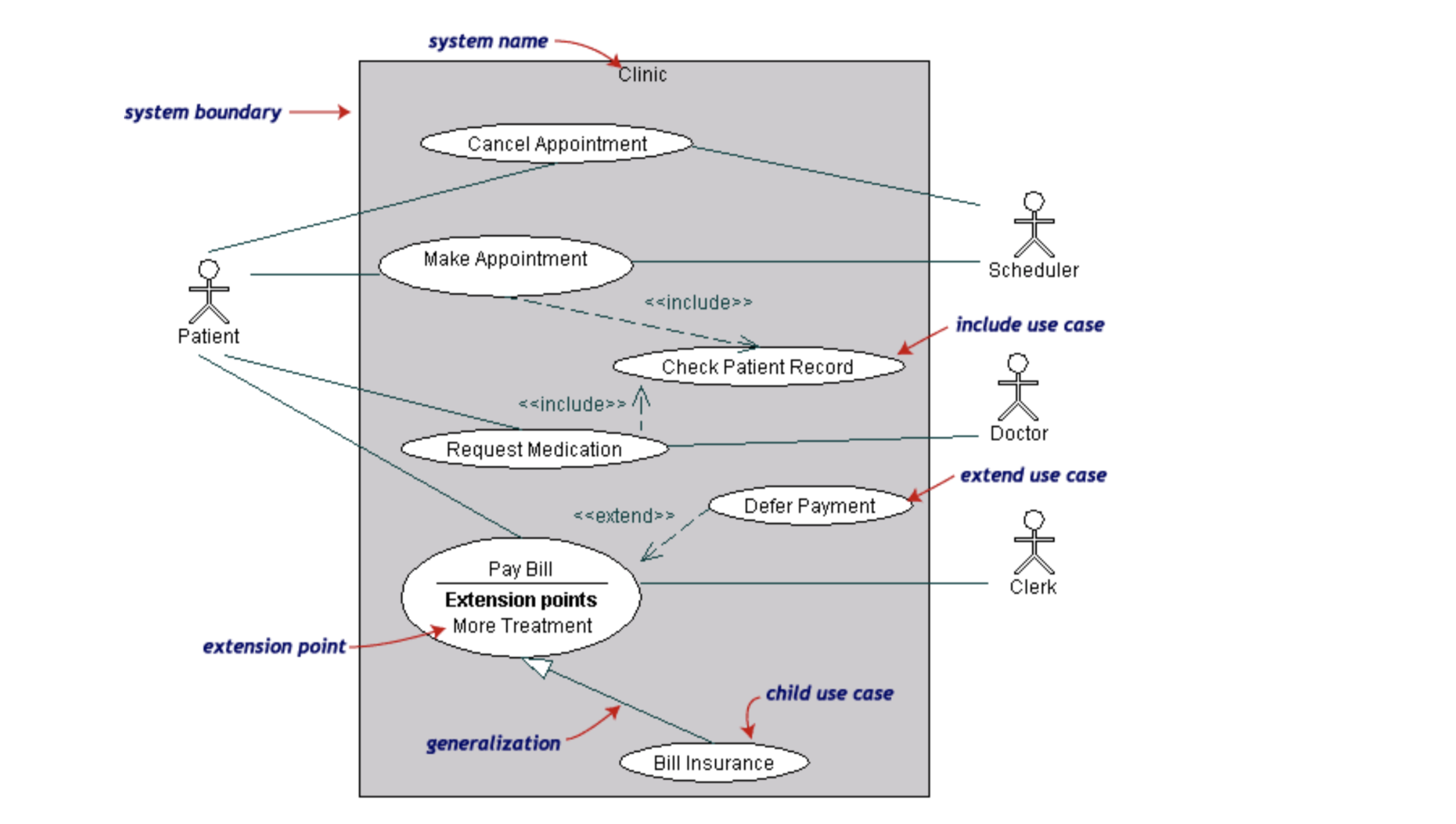
Use Case Diagrams
Use case diagrams model the functionality of system using actors and use cases.
- determining features (requirements)
- communicating with clients.
- generating test cases.
☛ System's boundary
Redundancy in Use Case Descriptions ----> Move to “include” Use Case
Special Case Use Cases
1) “bold” text was added
2) Reuse of description was cut-and-paste
3) In practice, not widely used
<extend> : reuse is optional and depend either on a runtime or system implementation decision
Collaboration Diagrams
Collaboration diagrams represent interactions between objects as a series of sequenced messages. Collaboration diagrams describe both the static structure and the dynamic behavior of a system.
State Diagrams
State diagrams describe the dynamic behavior of a system in response to external stimuli. Statechart diagrams are especially useful in modeling reactive objects whose states are triggered by specific events.
- behavioral state machine & protocol state machine (focusing on how to protocol & do not show behavior along transitions or inside states)
▻ A transition represents a change of state. __trigger[guard] / behavior
▻ The event causing the state change, or trigger, is written along the transition row.
▻ A state is a condition of being at a certain time.
Internal Behavior:
- Do behavior, written as do/behavior, is behavior that happens as long as the state is active.
- Entry behavior happens as soon as the state becomes active ==> entry/behavior
- Exit behavior happens immediately before the state becomes inactive ==> exit/behavior
Internal Transition: trigger[guard] / behavior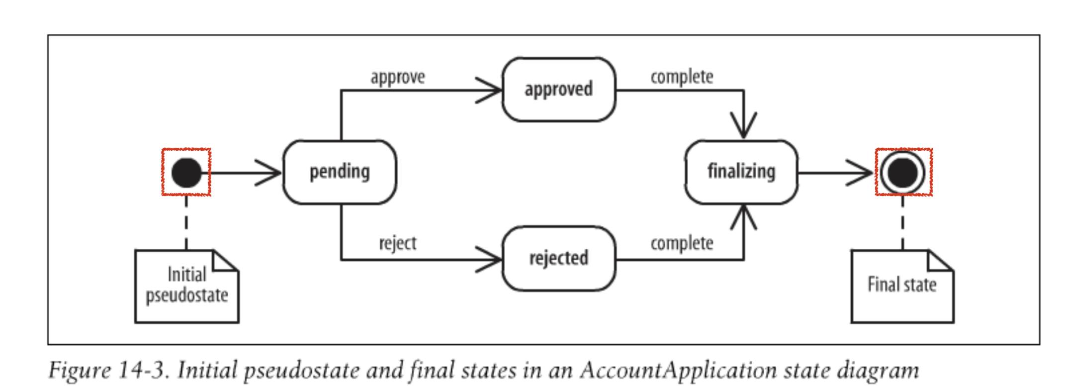
Package, Component, Deployment Diagrams
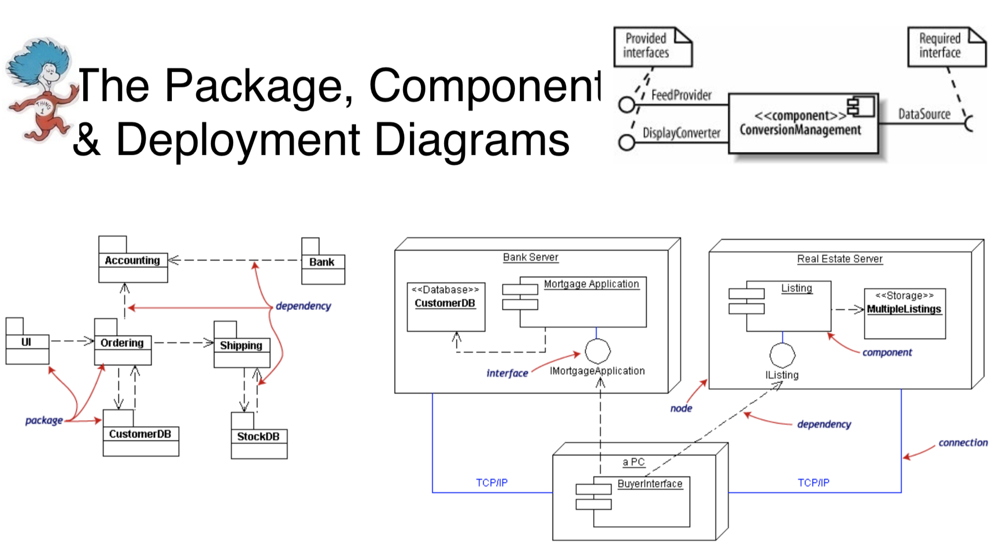
Package diagrams : are a subset of class diagrams, but developers sometimes treat them as a separate technique. Package diagrams organize elements of a system into related groups to minimize dependencies between packages.
Component diagrams : describe the organization of physical software components, including source code, run-time (binary) code, and executables.
Deployment diagrams : depict the physical resources in a system, including nodes, components, and connections.
Object Diagrams : Object diagrams describe the static structure of a system at a particular time. They can be used to test class diagrams for accuracy.
A UML diagram that shows instances of classes at a “snapshot" point in time.

Entity= Long Lived Information
Boundary= Actor/System Interaction
Control= Complex Computation or Algorithm
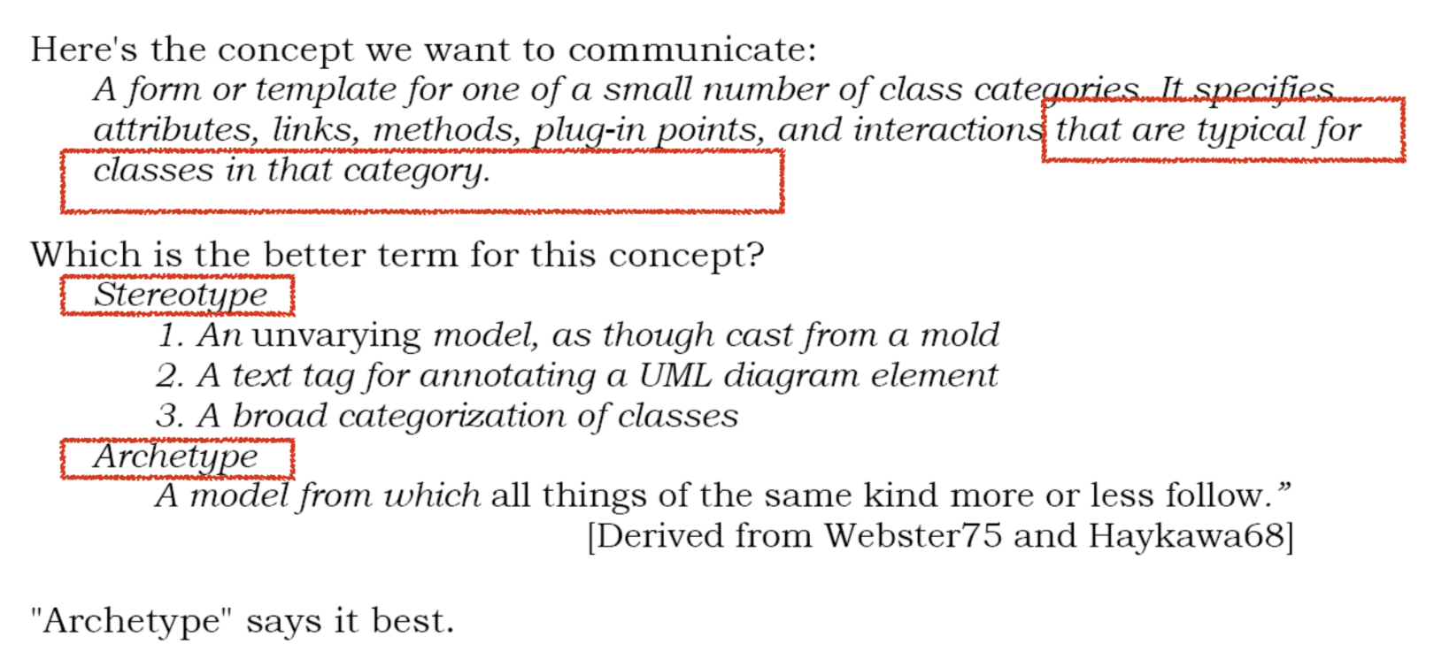 Archetype 原型;典型